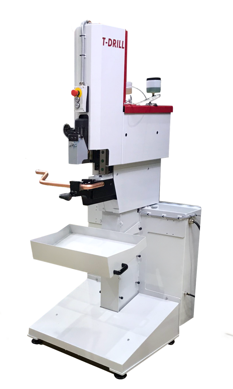
Industrial machine
S-28
S-28 forms branches in straight and bent tubes. Its slim tooling area helps reach workpieces where a larger unit would restrict access.

T-DRILL · Technology catalogue
From a portable tool to an integrated production line. Choose the result you need on the tube, explore the solutions and send us your production requirements.
TARGA helps select the machine, tooling and workpiece handling. Material, geometry and the production task provide the starting point. We can begin with a brief discussion, then agree on trials, configuration and implementation scope.
The branch is formed directly from the run tube wall. We select the process for the joint, material and production, from individual branches to series of manifolds.
Explore the process and models →FlangingForm a flange directly from the tube end. Compare F-200, F-400 and F-420e, then select the process, tooling and workpiece supports.
Explore the process and models →CuttingSelect chipless cutting for your input material, part length and next operation. TCC includes manual, coil and rack-loaded feeding.
Explore the process and models →End formingThe tube end shape determines the processing method. Select tool-based forming or spinning for the required geometry, material and production workflow.
Explore the process and models →WeldingT-InWeld performs welding on the inside of a tubular joint. We assess geometry, access and finished product quality requirements.
Explore the process and models →T-54 SST, T-54c, PLUS attachments, HFT tables and branch tube end preparation.
Select a set →FMS, feeding, positioning, production data and process integration.
Plan a system →T-DRILL catalogue
Configuration and availability are confirmed during selection.
35 items
Select 2–3 models from the same technology family to compare.
Industrial machine
S-28 forms branches in straight and bent tubes. Its slim tooling area helps reach workpieces where a larger unit would restrict access.
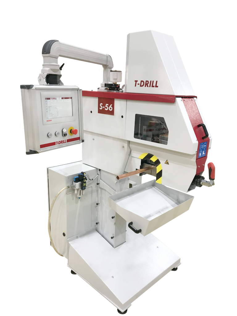
Industrial machine
S-56 prepares branches for welded and brazed joints. The cycle is selected for the joining method, material and tube geometry, from a stand-alone workstation to a configuration with a feeding system.
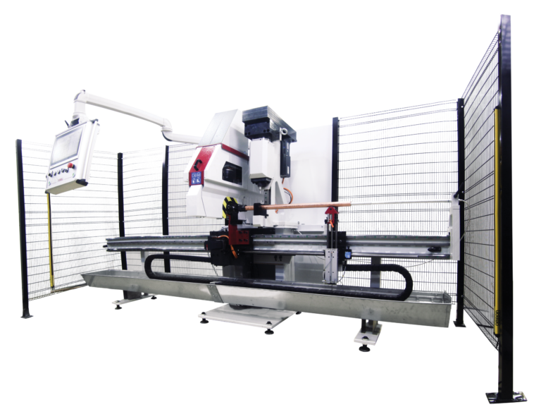
Industrial machine
S-56 PC combines hole punching with tube collaring. It prepares manifolds with different types of openings on one workstation.
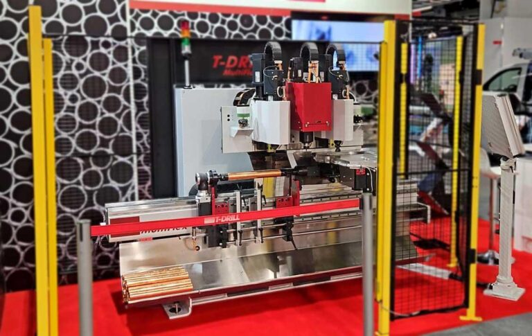
Industrial machine
S-56 MultiFlex produces manifolds using up to 3 processing units. The head arrangement is selected for branch diameters and brazed or welded joints.
Industrial machine
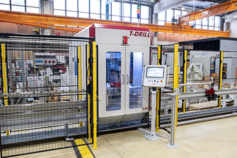
S-80 combines collaring with a tool magazine and automatic tube positioning in the AFT configuration. It suits repeat production where successive branches have different positions and diameters.
Industrial machine
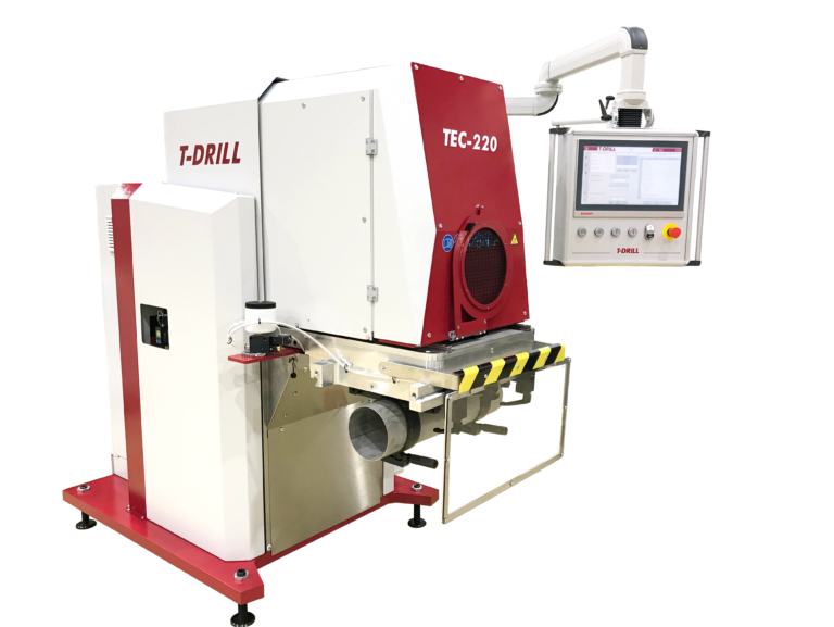
TEC-220 forms branches directly from the run tube wall. Hole milling, collaring and trimming take place at one workstation, for branches up to 219.1 mm outside diameter.
Industrial machine
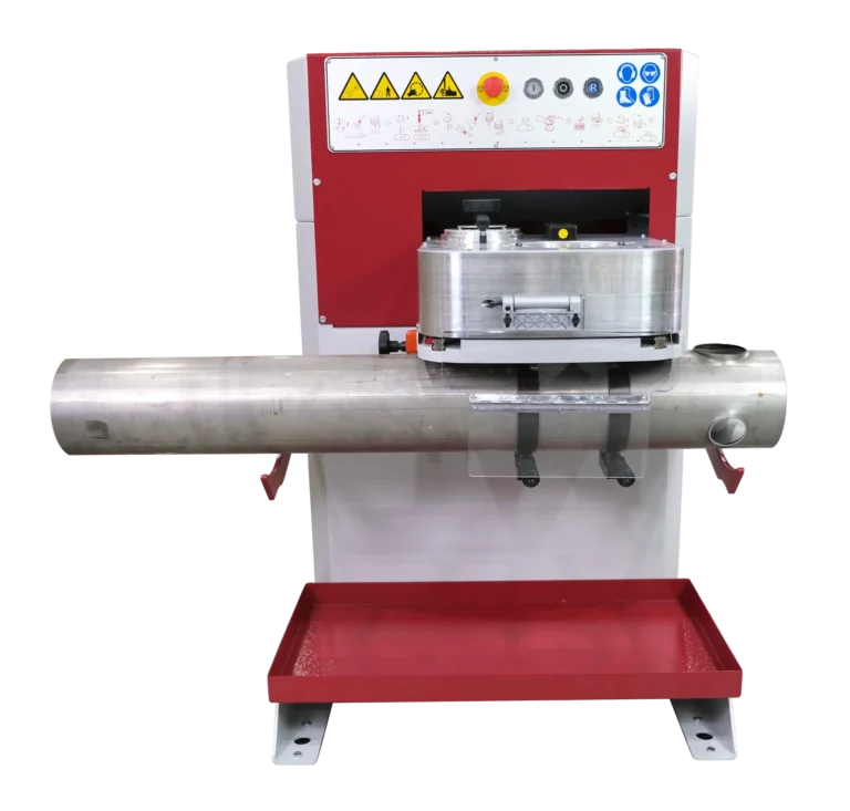
T-115 prepares the hole, forms the collar and trims its edge at one workstation. This compact tube prefabrication machine offers a larger range than a portable tool, with positioning selected for your production.
Industrial machine
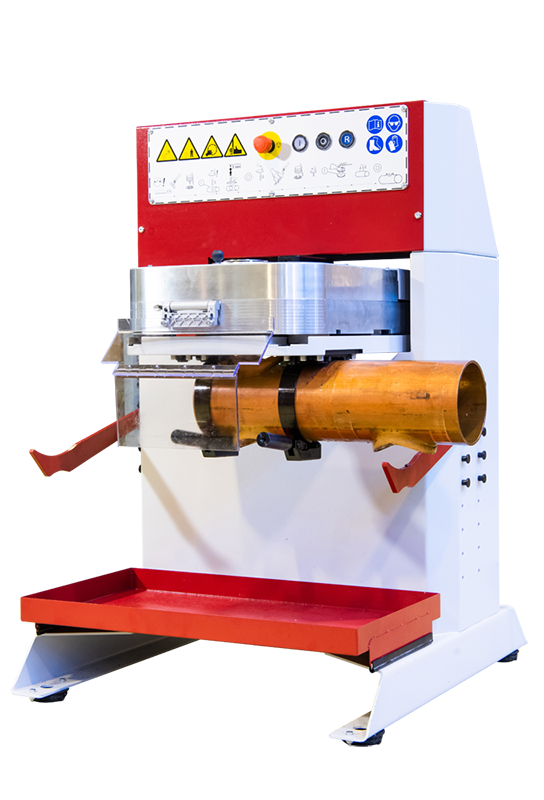
T-115 Cu prepares Ø18–108 mm branches in copper tubes. Separate tools make the pilot hole and form the collar for joining the branch tube.
Industrial machine
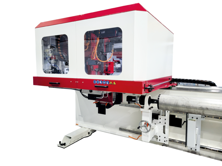
SEC-115 combines collaring with automatic tool changes. It provides a starting point for manifold production with multiple branches, different diameters and repeatable positions along the tube.
Industrial machine
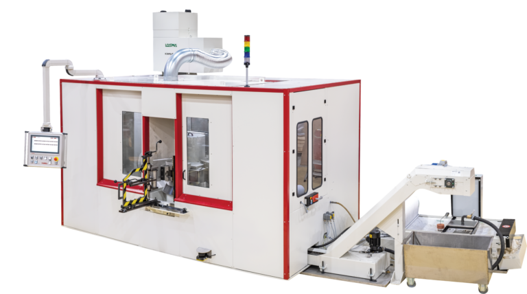
TBC-115 uses a rotary table and three units for hole milling, collaring and trimming. Successive stages can work in parallel on different parts.
Industrial machine
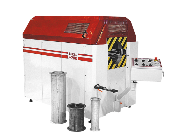
F-200 forms a flange directly on the tube end. Cold or hot forming, tools and supports are selected for the material, wall thickness and flange joint geometry.
Industrial machine
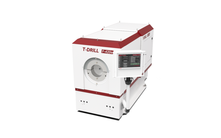
F-420e prepares the tube end for a joint with a loose backing flange. Electric servo drives and stored programmes support repeatable flanging. Cold or hot forming is selected for the material, diameter and wall thickness.
Industrial machine
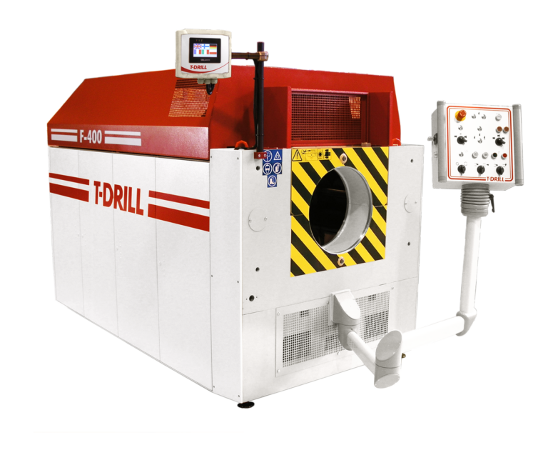
F-400 prepares flanged ends on Ø42.4–419 mm tubes. The COLD or HOT configuration is selected for the material and wall thickness; handling is selected for the workpiece length and weight.
Tube cutting machine
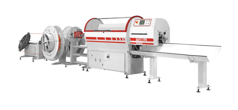
TCC-28 Coil combines decoiling, straightening and chipless tube cutting to programmed lengths. Line selection covers the material, coil and finished part unloading.
Tube cutting machine
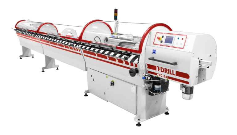
TCC-28 RL feeds tubes from a rackloader and cuts them chiplessly to programmed lengths. Selection also covers sorting and material remnant handling.
Tube cutting machine
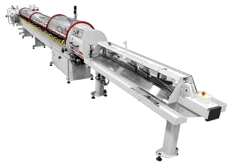
TCC-28 RL & Coil combines coil feeding with a rackloader for straight tubes. Both modes have separate material and equipment selection conditions.
Tube cutting machine
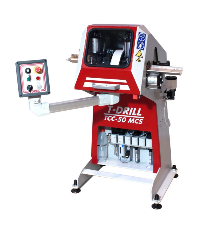
TCC-50 MCS is a chipless cutting workstation for smaller batches. The operator feeds the tube against a length stop and the machine performs the cutting cycle.
Tube cutting machine
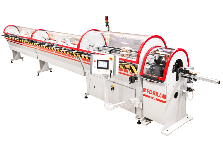
TCC-50 RL automates cutting of Ø8–50.8 mm straight tubes. The rackloader and sorter are selected for the input material and required part lengths.
Tube cutting machine
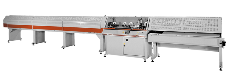
TCC-50 RL & Coil combines cutting of straight and coiled tubing. Capacity for each material route, lengths and equipment are agreed as one line configuration.
Tube cutting machine
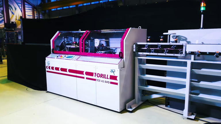
TCC-45 SVO uses servo-driven roller feeding for chipless cutting of coiled tubes. It is particularly useful for longer cut lengths and frequent length changes.
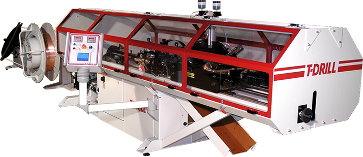
Cutting and end-forming line
TCC-45 EF3 combines chipless cutting and end forming in one system. Up to three tool strokes can prepare a profile without moving the part to a separate end former.
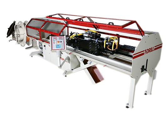
Cutting and end-forming line
TCC-45 EF8 combines tube cutting with a cycle of up to eight forming strokes. It allows a more complex end profile to be planned within one line.
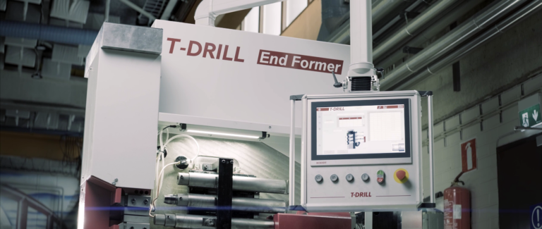
Tube end-forming machine
EFO-3e performs up to three forming strokes in a programmed cycle. Electric servo drives and tools selected from the drawing produce the required tube end profile.
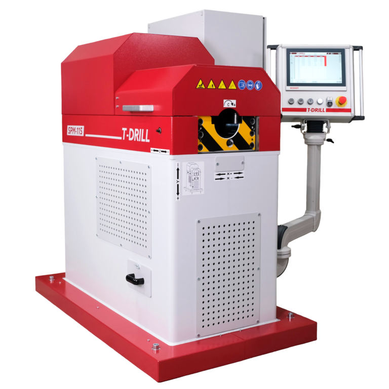
Spinning machine
SPM-115 closes the ends of copper and brass tubes with a flat profile. An electric servo drive follows the programmed cycle while a rotating tool forms the stationary tube.
Spinning machine
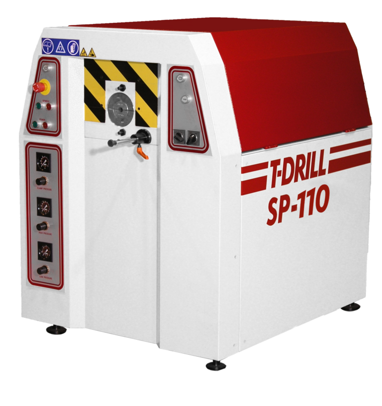
SP-110 is a spinning machine for copper tubes. The selected tool defines the end shape; capacity is checked separately for closing, reducing and expanding.
Industrial machine
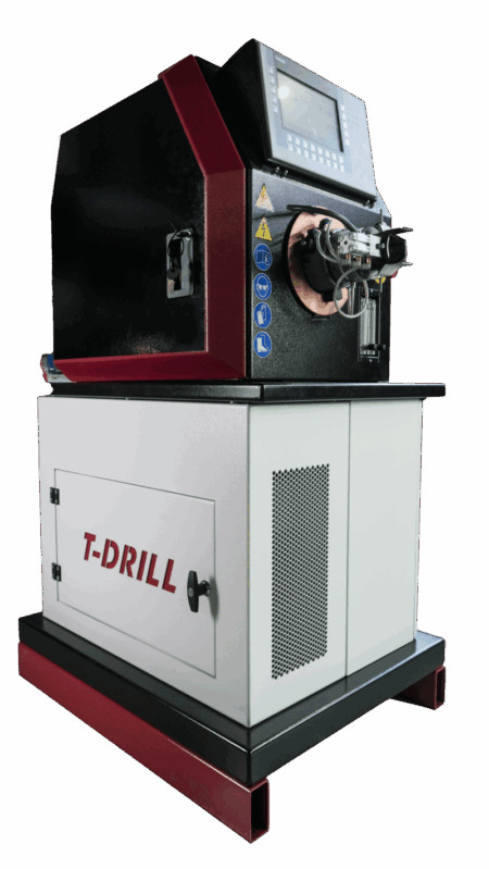
T-InWeld performs an automated TIG welding process from inside the tubular component. Selection starts with joint geometry, tool access and internal surface requirements.
Cordless portable tool
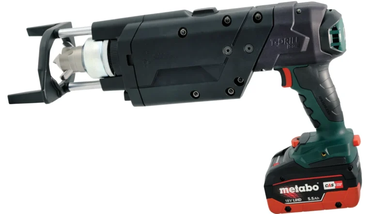
The cordless T-54c forms a collar directly in a copper tube. The branch tube is then inserted into the prepared outlet and brazed. The set is selected for tube diameters and wall thicknesses.
Corded portable tool
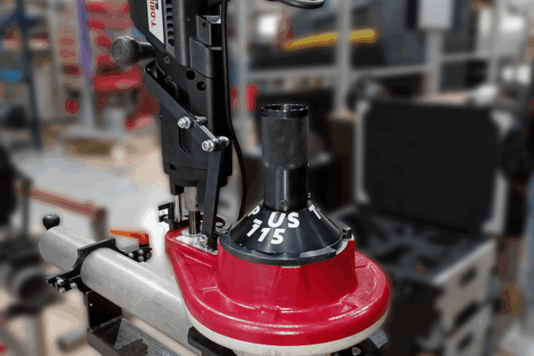
A corded system for collaring steel and stainless steel tubes. Tooling, clamping and equipment are selected for the workpiece geometry.
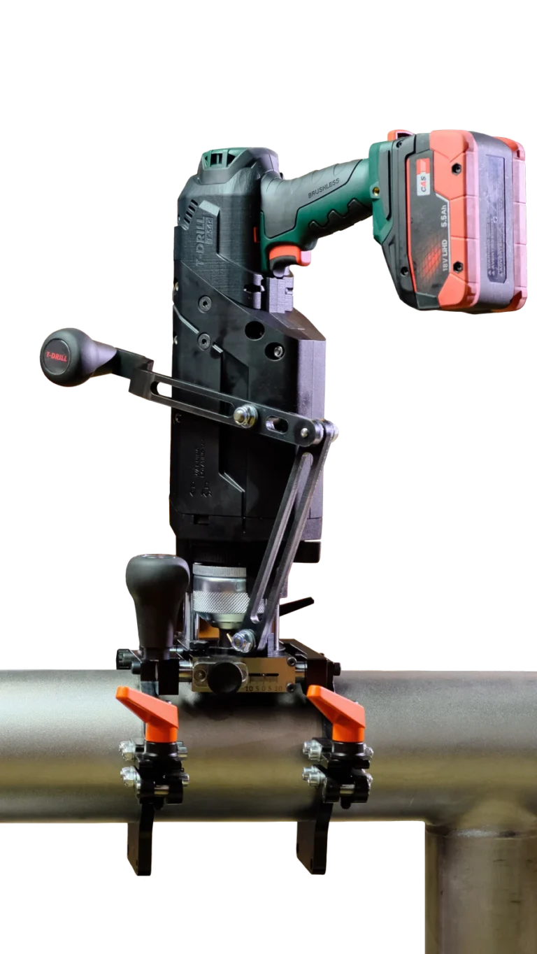
Cordless portable tool
T-54c SST combines a cordless drive with a clamping module for steel tubes. It forms a branch collar directly from the tube wall and then trims the edge for subsequent joining.
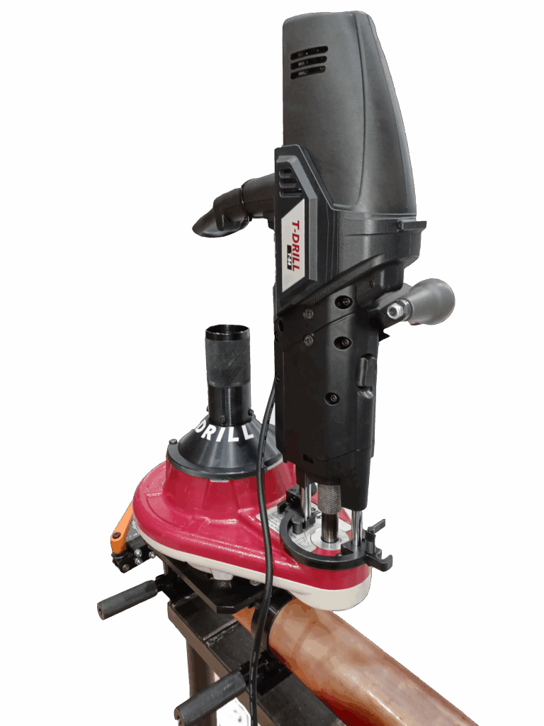
Range extension unit
PLUS 115 Cu extends the capabilities of a compatible T-54 family tool. The set forms Ø54–115 mm branches; tools and clamping are selected for the run tube.
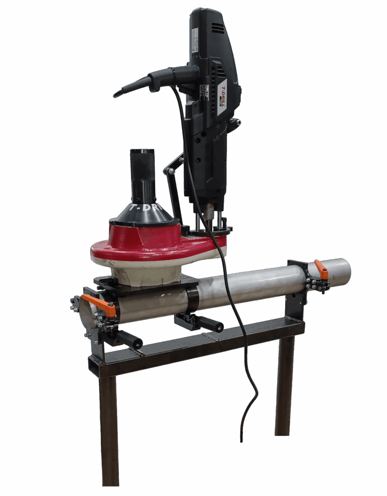
Range extension unit
PLUS 115 SST extends the capabilities of a compatible T-54 family tool. The set forms Ø48.3–114.3 mm branches; tools and clamping are selected for the run tube.
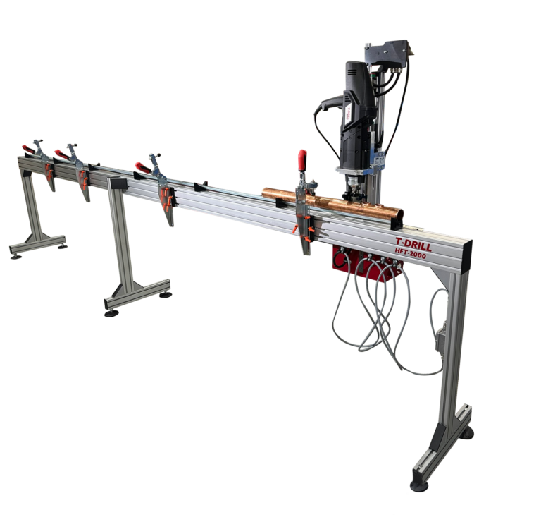
Modular work table
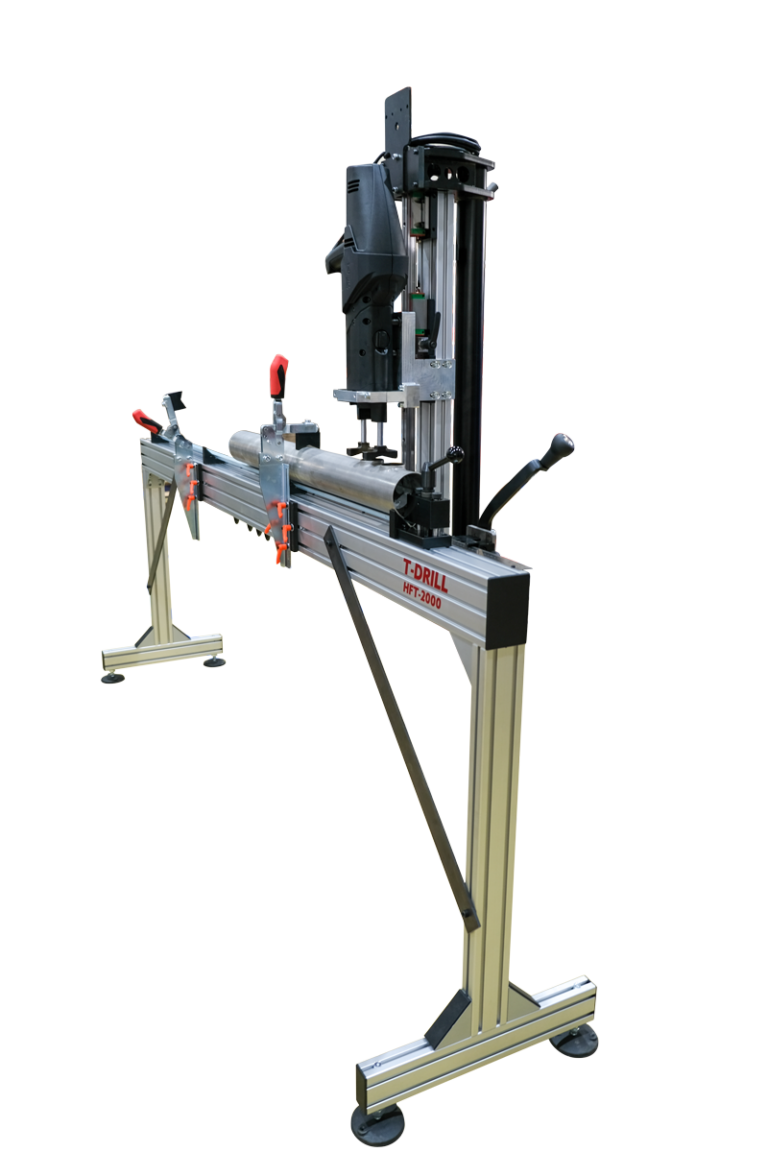
HFT-2000 organises tube support and positioning when forming multiple branches. The nominal 2000 mm working range can be extended with additional modules.
Modular work table
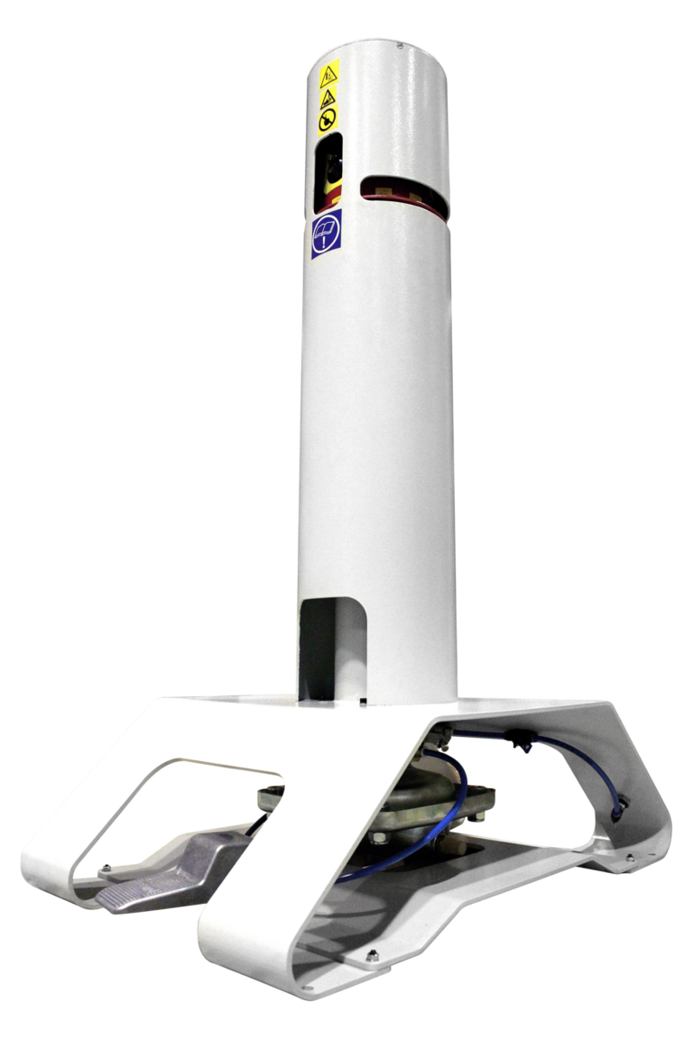
HFT-2000 SS organises tube support and positioning when forming multiple branches. The nominal 2000 mm working range can be extended with additional modules.
Tube end notching tool
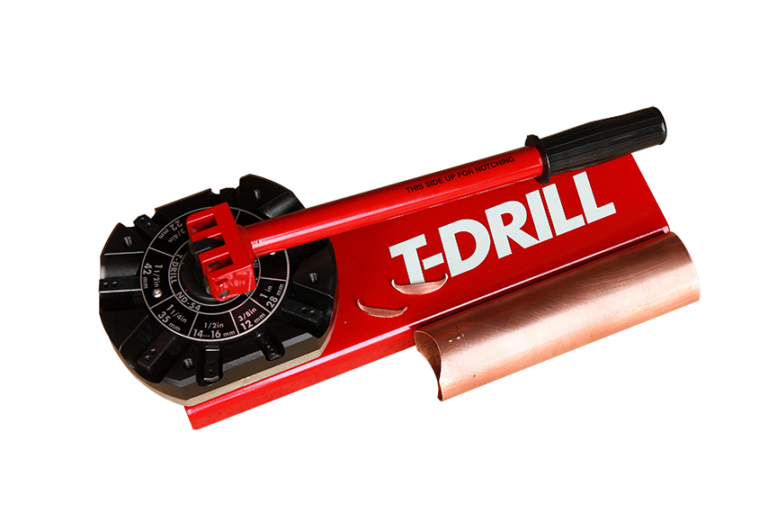
PND-54 notches and dimples the branch tube end before insertion into the formed collar. It helps set insertion depth and maintain the joint flow area.
Tube end notching tool
ND-54 notches and dimples the branch tube end before insertion into the formed collar. It helps set insertion depth and maintain the joint flow area.
No results. Change the name or filter.
Selection with TARGA
Choose a process or describe the finished part. We will help identify the equipment family and the data required to confirm the configuration.
The catalogue includes machines, portable tools, attachments and tables. Production systems and custom solutions are discussed separately, with their scope adapted to the project.
Yes. Working with T-DRILL’s engineering team, we can develop a machine or system adapted to the workpiece, production organisation and required operations. The scope follows the project requirements.