Industrial machines
Workstation selection for the material, tube geometry and joining method. Different models and configurations serve different production tasks.

T-DRILL · Collaring
The branch is formed directly from the run tube wall. We select the process for the joint, material and production, from individual branches to series of manifolds.
Collaring draws a collar around a hole in the tube wall. The branch tube is joined to it by brazing or welding, according to the design. The process can reduce the use of separate tees and the number of joints. Branch geometry and edge preparation depend on the selected joining method.
Workstation selection for the material, tube geometry and joining method. Different models and configurations serve different production tasks.
Portable tools, attachments, tables and branch tube end preparation equipment. The set is selected as compatible components.
T-DRILL catalogue
Configuration and availability are confirmed during selection.
19 items
Select 2–3 models from the same technology family to compare.
Industrial machine
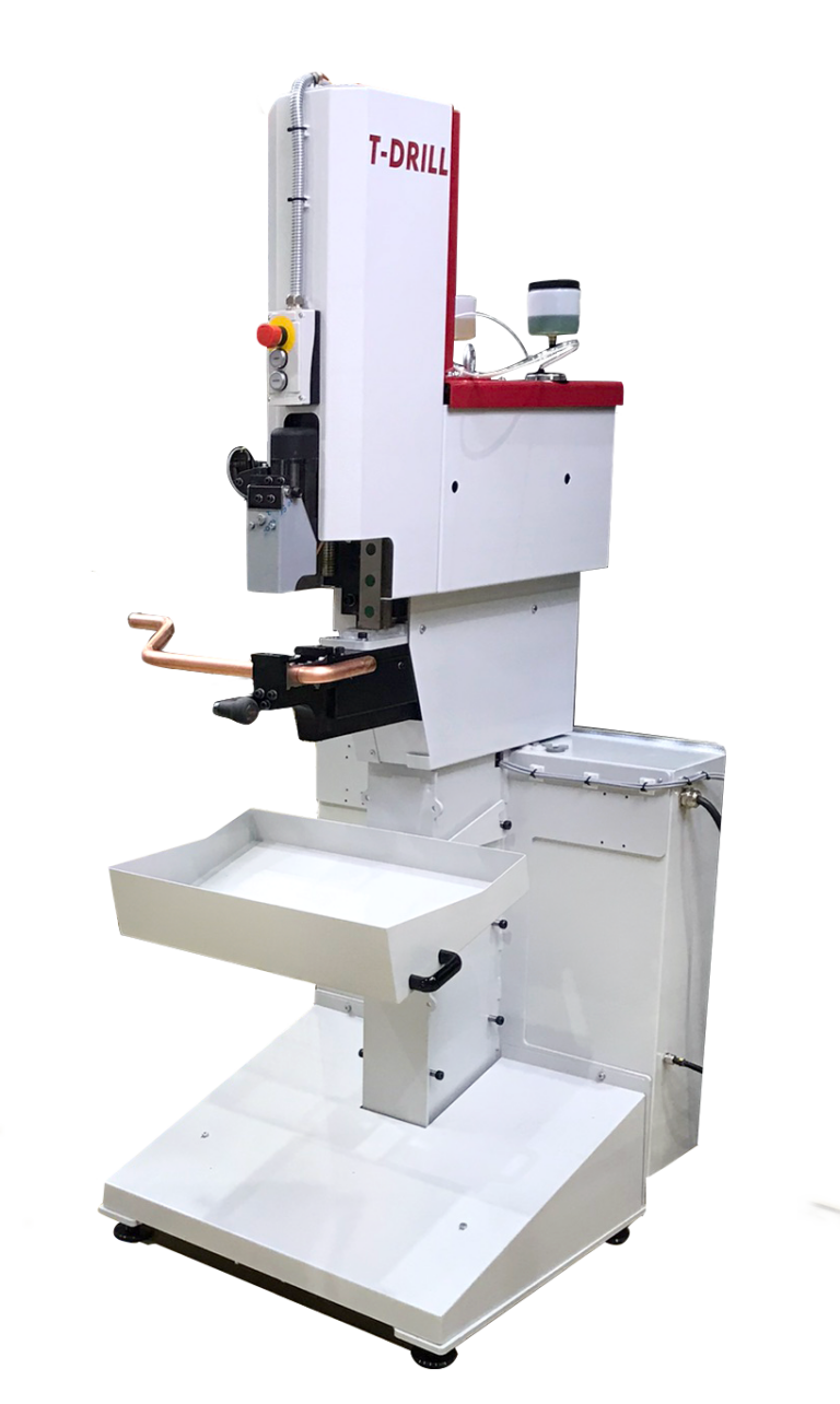
S-28 forms branches in straight and bent tubes. Its slim tooling area helps reach workpieces where a larger unit would restrict access.
Industrial machine
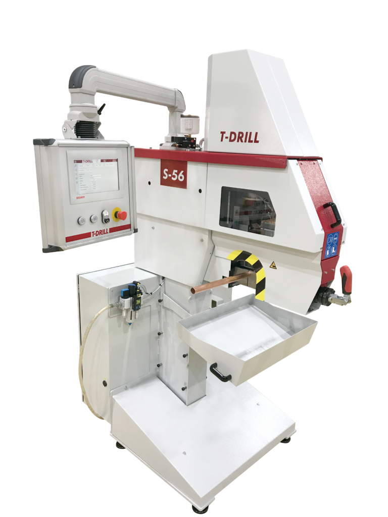
S-56 prepares branches for welded and brazed joints. The cycle is selected for the joining method, material and tube geometry, from a stand-alone workstation to a configuration with a feeding system.
Industrial machine
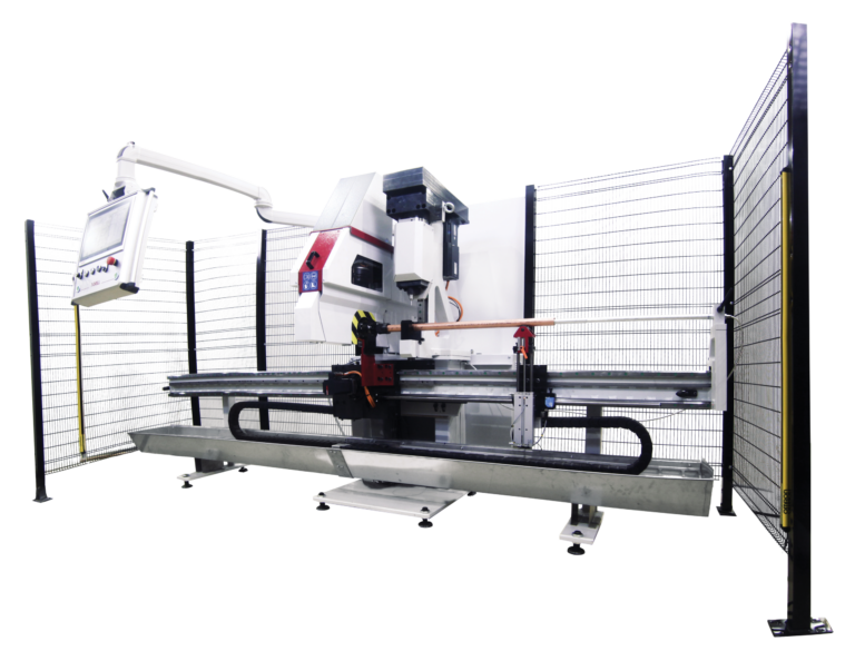
S-56 PC combines hole punching with tube collaring. It prepares manifolds with different types of openings on one workstation.
Industrial machine
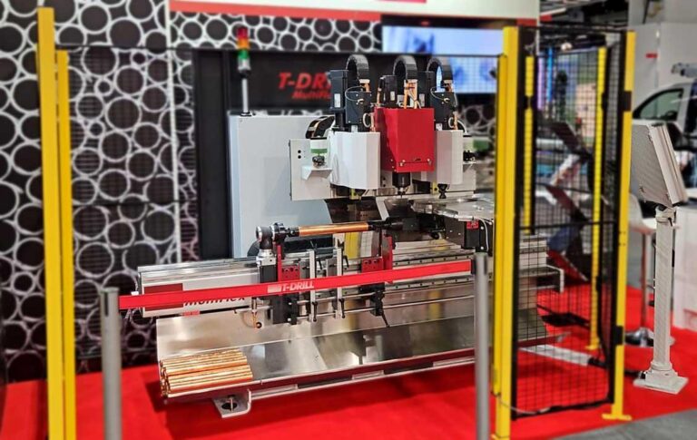
S-56 MultiFlex produces manifolds using up to 3 processing units. The head arrangement is selected for branch diameters and brazed or welded joints.
Industrial machine
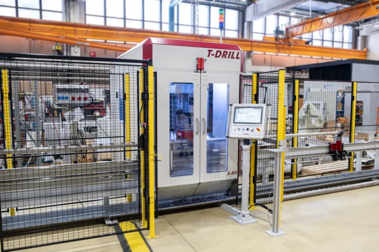
S-80 combines collaring with a tool magazine and automatic tube positioning in the AFT configuration. It suits repeat production where successive branches have different positions and diameters.
Industrial machine
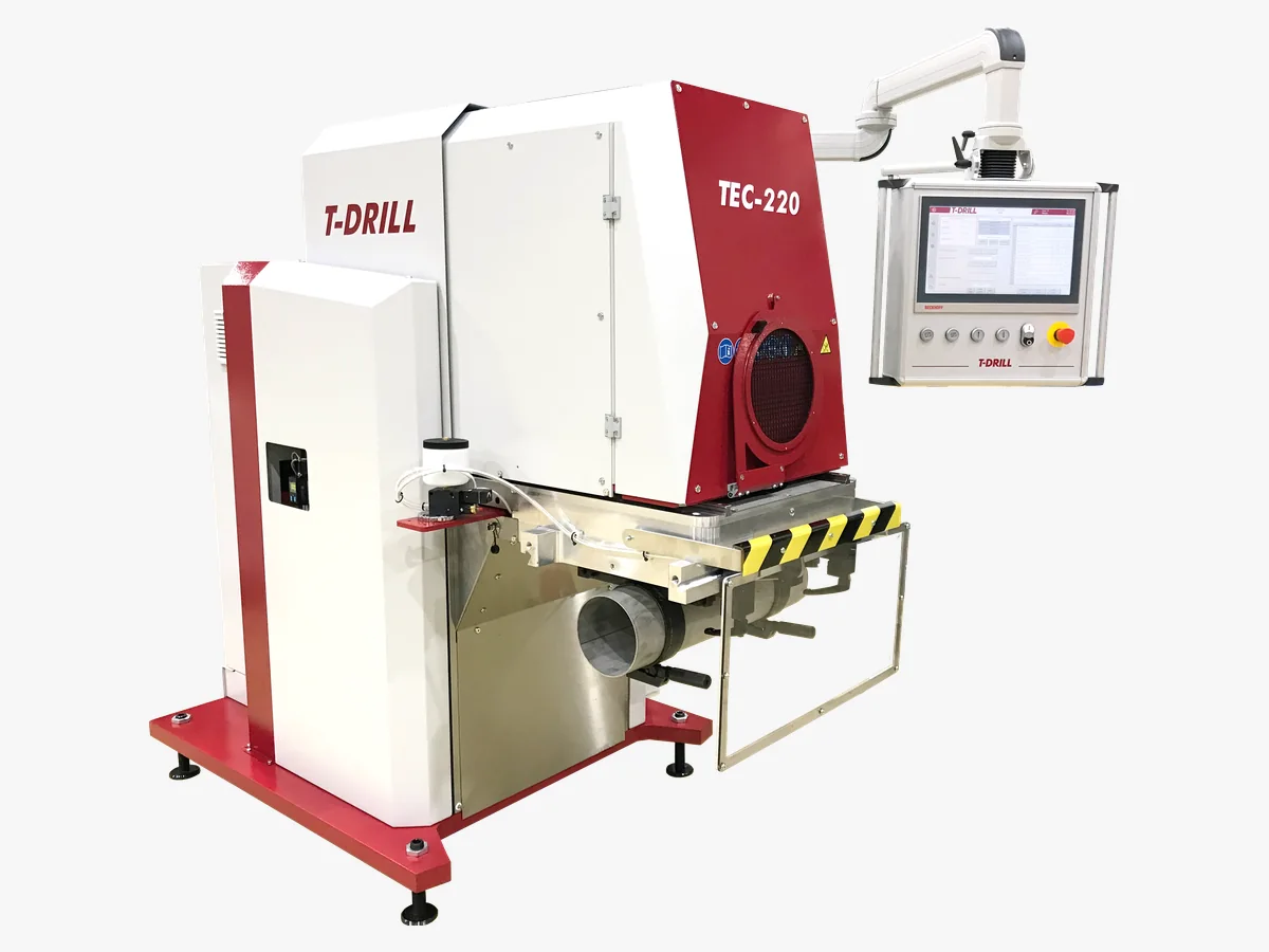
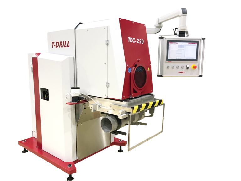
TEC-220 forms branches directly from the run tube wall. Hole milling, collaring and trimming take place at one workstation, for branches up to 219.1 mm outside diameter.
Industrial machine
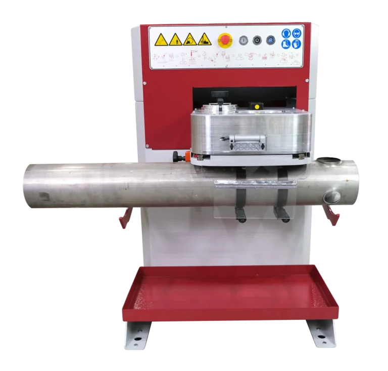
T-115 prepares the hole, forms the collar and trims its edge at one workstation. This compact tube prefabrication machine offers a larger range than a portable tool, with positioning selected for your production.
Industrial machine
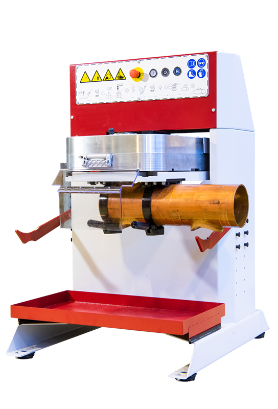
T-115 Cu prepares Ø18–108 mm branches in copper tubes. Separate tools make the pilot hole and form the collar for joining the branch tube.
Industrial machine
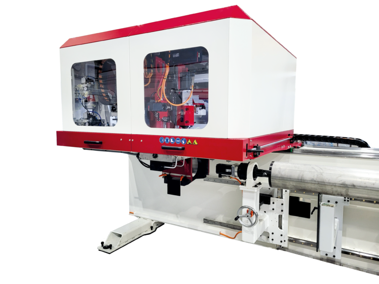
SEC-115 combines collaring with automatic tool changes. It provides a starting point for manifold production with multiple branches, different diameters and repeatable positions along the tube.
Industrial machine
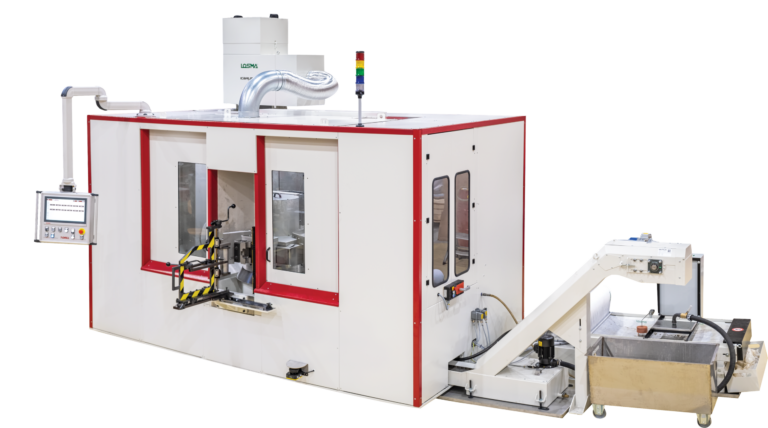
TBC-115 uses a rotary table and three units for hole milling, collaring and trimming. Successive stages can work in parallel on different parts.
Cordless portable tool
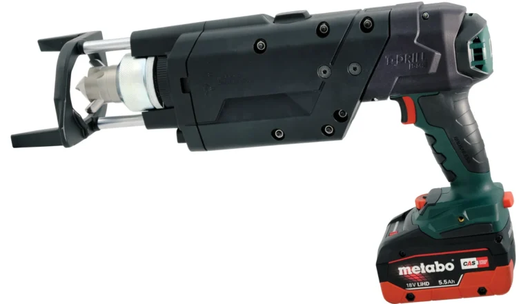
The cordless T-54c forms a collar directly in a copper tube. The branch tube is then inserted into the prepared outlet and brazed. The set is selected for tube diameters and wall thicknesses.
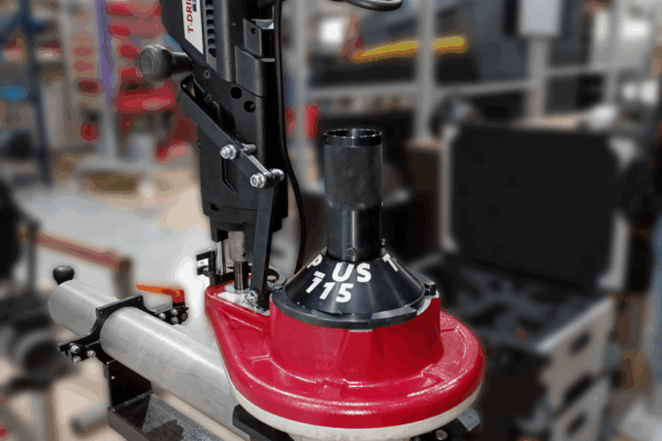
Corded portable tool
A corded system for collaring steel and stainless steel tubes. Tooling, clamping and equipment are selected for the workpiece geometry.
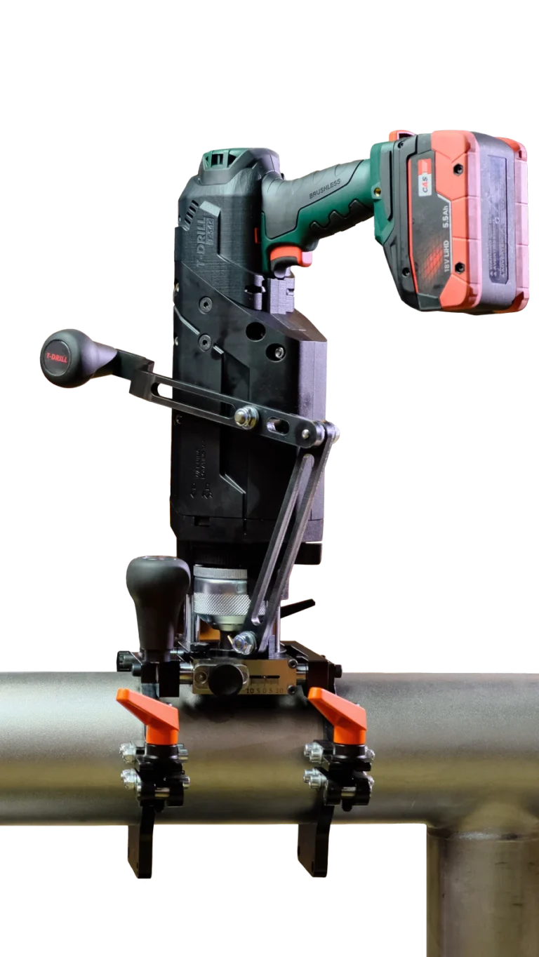
Cordless portable tool
T-54c SST combines a cordless drive with a clamping module for steel tubes. It forms a branch collar directly from the tube wall and then trims the edge for subsequent joining.
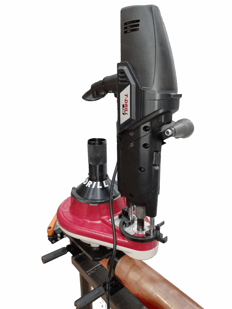
Range extension unit
PLUS 115 Cu extends the capabilities of a compatible T-54 family tool. The set forms Ø54–115 mm branches; tools and clamping are selected for the run tube.
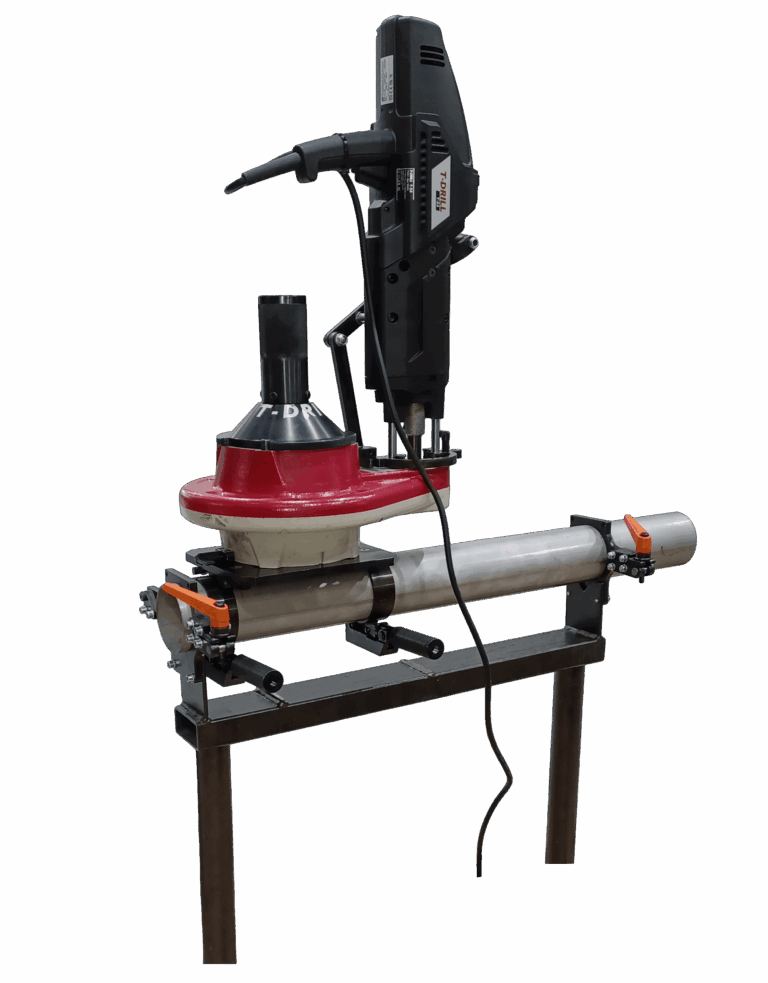
Range extension unit
PLUS 115 SST extends the capabilities of a compatible T-54 family tool. The set forms Ø48.3–114.3 mm branches; tools and clamping are selected for the run tube.
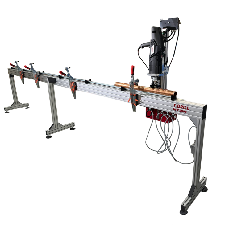
Modular work table
HFT-2000 organises tube support and positioning when forming multiple branches. The nominal 2000 mm working range can be extended with additional modules.
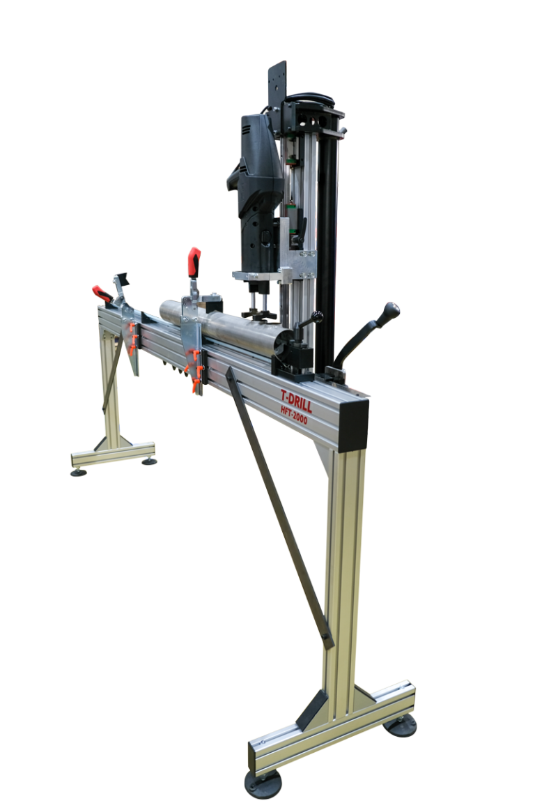
Modular work table
HFT-2000 SS organises tube support and positioning when forming multiple branches. The nominal 2000 mm working range can be extended with additional modules.
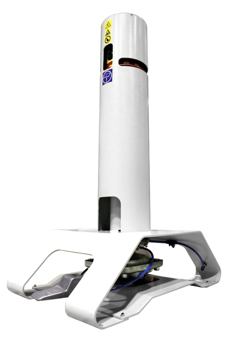
Tube end notching tool
PND-54 notches and dimples the branch tube end before insertion into the formed collar. It helps set insertion depth and maintain the joint flow area.
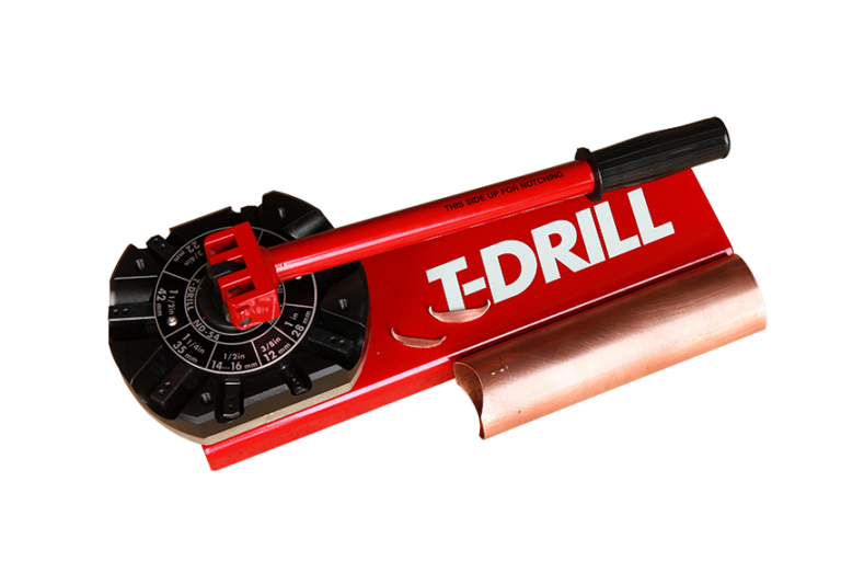
Tube end notching tool
ND-54 notches and dimples the branch tube end before insertion into the formed collar. It helps set insertion depth and maintain the joint flow area.
No results. Change the name or filter.
Selection with TARGA
It can be an alternative where the material, geometry and joint requirements permit a suitable branch to be formed. Selection is confirmed for the actual workpiece.
Wall thicknesses, material grade, diameter ratios, tool access and joining method are also required. These define the configuration and any need for trials.
Yes. If an existing configuration does not suit the task, we work with T-DRILL’s engineering team to assess a solution adapted to the customer’s geometry and production.