
T-DRILL · Collaring
S-56 PCHole punching and tube collaring.
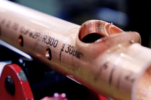
S-56 PC combines hole punching with tube collaring. It prepares manifolds with different types of openings on one workstation.
Selection, implementation and support in Poland — TARGA.
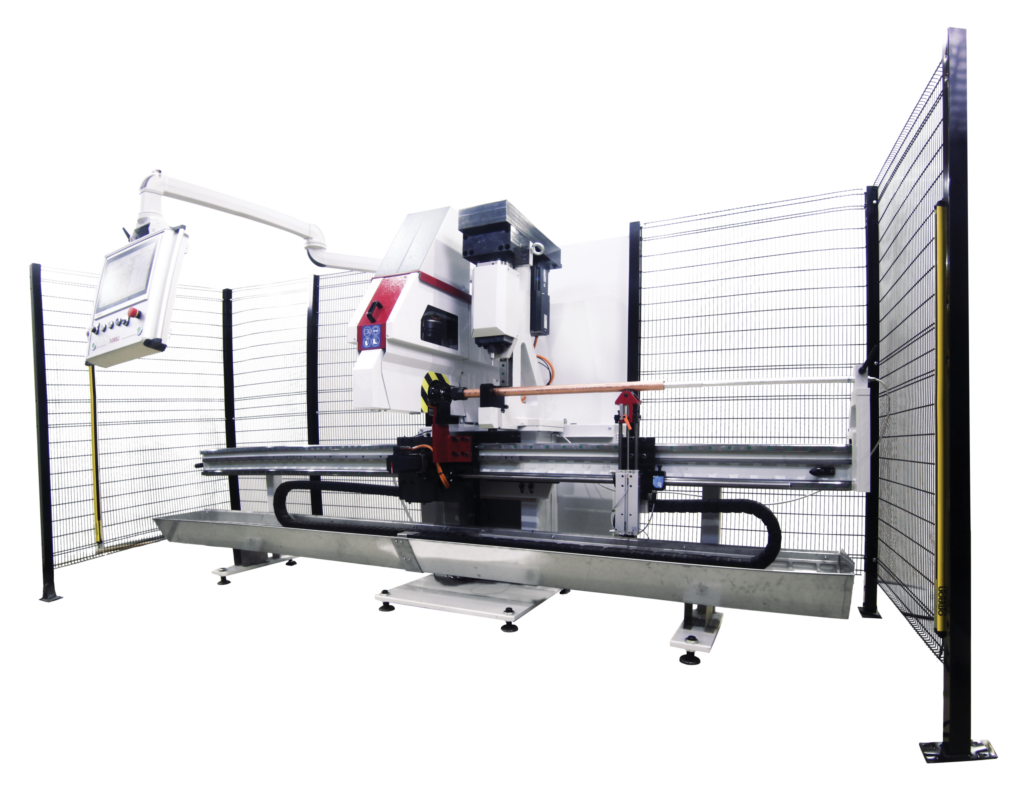
From workpiece to process
Applications for S-56 PC
Developed for applications including CuFe2P HVACR manifolds. Combining punching and collaring reduces transfers between operations. Each method has its own capacity and requires suitable tooling.
How does the process work?
Manifold programme
Assign punching or collaring to each opening.
Clamping
Locate and position the tube.
Operations
Perform the planned cycles within one system.
Working range
Specifications and selection conditions
| Punching — hole diameter | Ø5–22.5 mm |
|---|---|
| Drilling / collaring / trimming | Ø12–58 mm outside diameter |
| Drilling / collaring | Ø6–54 mm inside diameter |
| Run tube | Ø16–108 mm outside diameter |
| CuFe2P — wall thickness | Up to 3.6 mm in the described configuration; not a limit for all materials and diameters |
| Materials | Steel, stainless steel, Al, Cu, CuNi and CuFe2P, subject to selection |
| Compressed air | 6–9 bar |
Configuration
Equipment selected for production
Punching and collaring tools, clamps, positioning and tube handling are specified for the manifold programme. The PC designation alone does not define the complete equipment package.
Machine and workpiece
Manufacturer resources
Brochures describe configurations from the stated edition. We confirm the offered scope for your workpiece.
Watch the equipment in operation
Manufacturer videos may show optional equipment. Playing a video connects to YouTube.
The new S-56 PC 1500 Punching and Collaring Unit. Two methods, one unit, double efficiency.
Open on YouTube ↗What do we need for selection?
Send the material, wall thickness and manifold drawing, identifying punched holes and formed branches.
Before you choose
Do punching and collaring produce the same joint?
Punching makes a hole; collaring forms a branch from the tube material. The method is selected for the joint design.
Is 3.6 mm a universal wall thickness limit?
The brochure gives this value for the described CuFe2P configuration. Other materials and combinations require separate selection.
Explore related solutions
Industrial machine
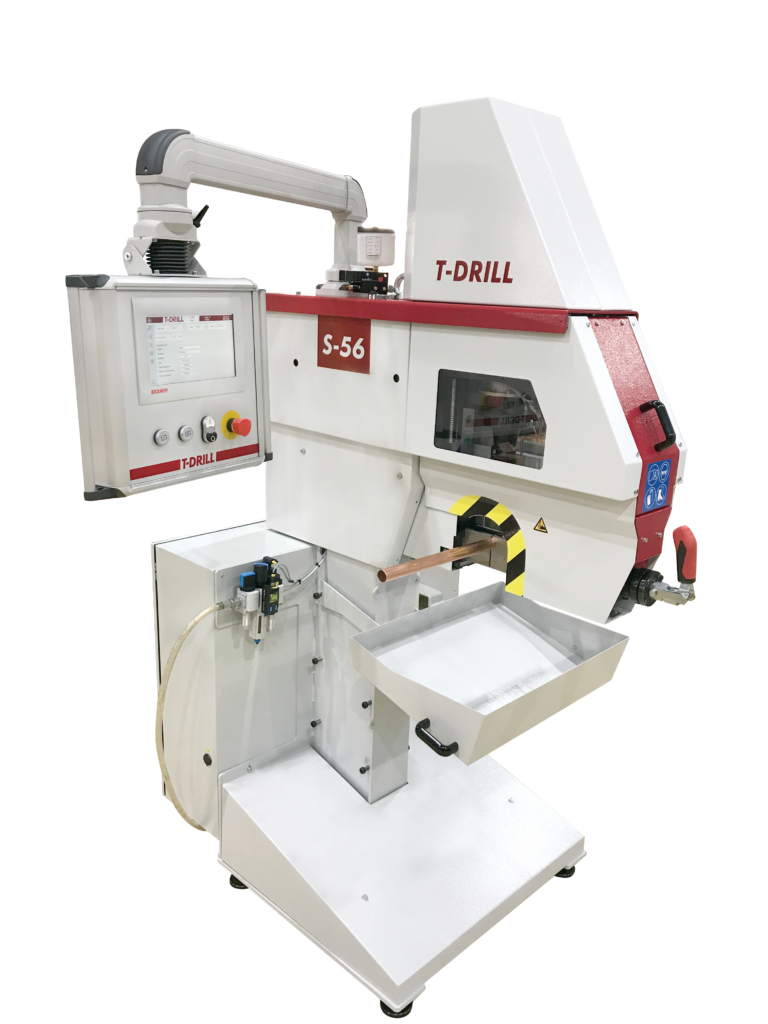
S-56
S-56 prepares branches for welded and brazed joints. The cycle is selected for the joining method, material and tube geometry, from a stand-alone workstation to a configuration with a feeding system.
Industrial machine
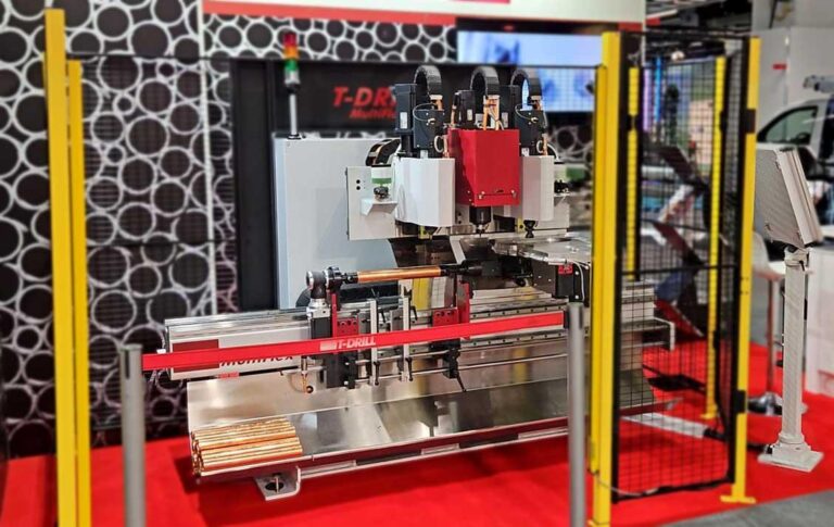
S-56 MultiFlex
S-56 MultiFlex produces manifolds using up to 3 processing units. The head arrangement is selected for branch diameters and brazed or welded joints.
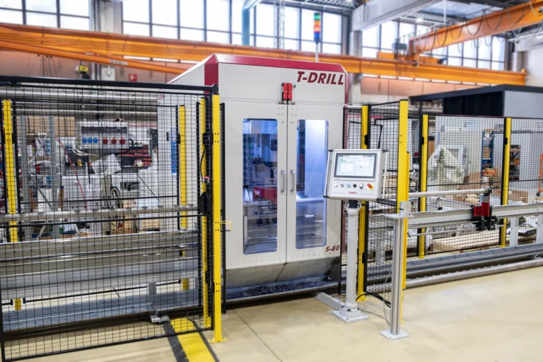
Industrial machine
S-80
S-80 combines collaring with a tool magazine and automatic tube positioning in the AFT configuration. It suits repeat production where successive branches have different positions and diameters.